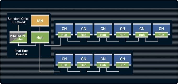
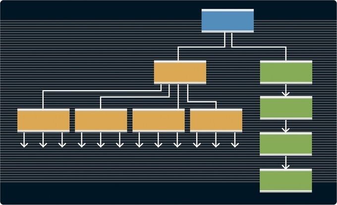
One of the most important characteristics of Ethernet – and therefore POWERLINK – is that users are completely free to choose any type of network topology whatsoever. Star, tree, daisy chain or ring structures – any combination of these topologies is possible on a network without configuration. There is also no binding interdependence between logical links in the application and the physical layout. Changes to the network, including modifications made on the fly, can be implemented at any time and in any way without compromising the application.
UNIQUE ADRESSING
UNIQUE ADRESSING
One of the most important characteristics of Ethernet – and therefore POWERLINK – is that users are completely free to choose any type of network topology whatsoever. Star, tree, daisy chain or ring structures – any combination of these topologies is possible on a network without configuration. There is also no binding interdependence between logical links in the application and the physical layout. Changes to the network, including modifications made on the fly, can be implemented at any time and in any way without compromising the application.
HOT PLUGGING
HOT PLUGGING
Hot plugging refers to connecting or disconnecting nodes from a network without compromising network functionality or having to reboot in order to use added or replaced nodes.
POWERLINK provides unlimited support for hot plugging. Upgrades or replacing devices locally does not impair real-time performance, and it is not necessary to reboot the system. This makes it possible for operators to replace sensors or add mechatronic units without having to shut down the network first – a basic prerequisite for using the protocol in the process industry or in modular machinery and plants.
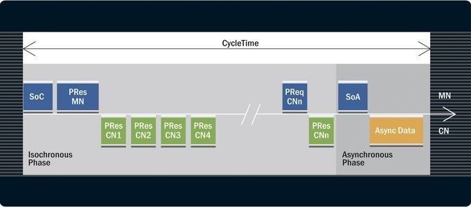
ASYNCHRONOUS DATA
ASYNCHRONOUS DATA
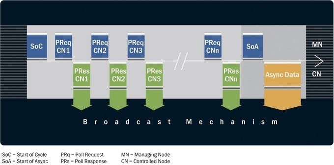
The isochronous phase of the POWERLINK cycle for time-critical payload data transfer is followed by the asynchronous phase, which completes the cycle. In this phase, non-time-critical data packets can be transmitted in standard Ethernet frames. Any type of data can be transferred during the asynchronous phase, e.g. service data objects (SDOs) for device configuration and diagnostics, application data such as surveillance camera feeds and even protocols like TCP/IP for device configuration or maintenance from a web browser. This also provides a way to connect nodes that are not real-time capable to the network in addition to integrating components or plant segments equipped with other fieldbus interfaces. In the latter case, devices are connected to a POWERLINK node via a gateway; their non-POWERLINK fieldbus data is then transmitted in the asynchronous phase of the POWERLINK cycle. This mode of data transfer is extremely vital for hot plugging, in which new devices or replacements identify themselves by sending their device data to the managing node during the asynchronous phase.
DIRECT CROSS-TRAFFIC
Ethernet – and POWERLINK – communication works according to the broadcast principle: Every node is free to broadcast its own data across the network, and every other node is generally able to receive these broadcasts. Nodes use the destination address included with the data packets to determine whether the data is intended for them. This transmission principle enables direct cross-traffic among controllers, which means that communication does not have to be routed through a dedicated master or managing node. In synchronized production segments, for instance, this feature makes it possible to synchronize the rotary encoders on every drive with a master encoder. For distributed safety architectures, direct cross-traffic among safety components is a basic prerequisite. The advantages are many: time savings, simplified systems and a reduction in control tasks that allows the use of less expensive controllers in many areas.
MULTIPLEXING
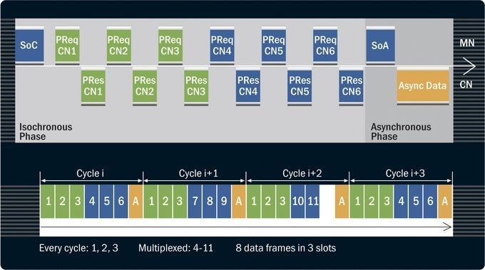
Multiplexing optimizes bandwidth use in the isochronous phase. Since requirements on data sampling intervals vary from application to application, not all controlled nodes must be polled in every cycle. While many motion control applications, for example, must constantly provide drives with information and poll their feedback data in every cycle, sensor data only has to be polled once every three cycles for temperature measurement.
With multiplexing, controlled nodes with low priority data share a time slot within the isochronous phase. They take turns so that one device utilizes the first, a second device the second and the third device the third cycle (every three cycles) to transfer their respective data. The MN assigns and manages shared time slots for these groups of nodes.
POLL RESPONSE CHAINING
The POWERLINK protocol also incorporates the "poll response chaining" feature.
Instead of querying CNs sequentially using PReq frames, the CNs are queries all at once by the PResMN frame, which is sent as a multicast. This increases performance if several nodes with only a small amount of process data are connected.
This feature is ideal for centralized control modes such as robot applications with a centrally closed velocity or current control loop.
REDUNDANCY
POWERLINK supports two types of redundancy: medium redundancy and master redundancy.
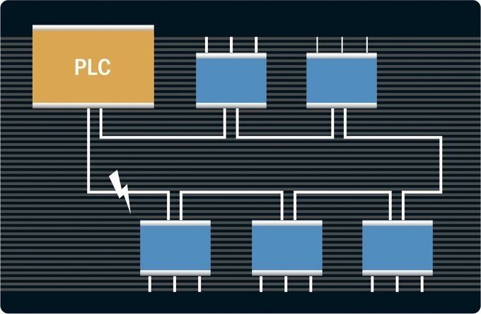
Ring redundancy
Classic ring redundancy is a simple and economical option in machine manufacturing. Applications are connected in the form of a ring, with both outer ends of the data line running through the network connected to the controller. For this layout, an extra data cable suffices to convert a daisy chain of applications into a ring, provided that the controller has two interfaces that support redundant operation. When a line failure is detected, the system switches from the failed data line to the redundant data line within a single cycle. This type of redundancy is typically used for solutions involving a considerable amount of mechanical stress.
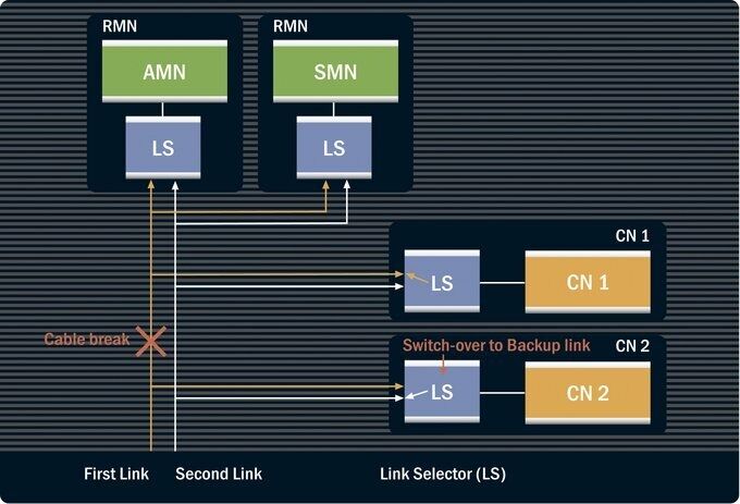
Complete medium redundancy
Complete medium redundancy
Critical systems require high-availability features, including complete medium redundancy.
With POWERLINK, complete medium redundancy is achieved through the use of two different physical networks. The same redundant information is then transferred on both networks at the same time. In the event of network failure, the switchover is instantaneous and does not require downtime or reconfiguration. Each node is linked to both physical networks via a link selector (LS).
Master Redundancy
Master Redundancy
The second type of redundancy is full master (or managing node) redundancy, which plays a key role in high-availability systems and is used for energy systems in the process industry. Master redundancy is based on two or more redundant managing nodes at the top of the network hierarchy. Only one of these nodes serves as an active managing node; the others remains on hot standby and act as controlled nodes from the active managing node's point of view. The only difference between a standby MN and a CN is that a standby MN continuously monitors all network and CN functions so that it can assume the function of the active MN at any time without rebooting. In an emergency, POWERLINK Node ID 240 – reserved by the MN – is transferred to the closest redundant MN on the fly. This type of redundancy allows for a wide range of topologies. In each case, all basic POWERLINK characteristics such as minimal reaction times, real-time synchronization, high bandwidth and simple diagnostics continue to be fully available.
EMC ROBUSTNESS
New machines include countless electronic power components that are not only powerful, but also a pervasive source of broadband electromagnetic interference. Since industrial Ethernet networks are becoming an integral part of machines and industrial plants, the close proximity of power electronics and network lines may cause problems that can only be solved by robust communication technology. As the machine's nervous system, the communication network is vital for the machine to function correctly. As a result, having a network with excellent EMC robustness is a critical requirement for machine builders. Theoretical studies published in Industrial Ethernet Book demonstrate that POWERLINK features excellent robustness against EMC. The results of this study have also been confirmed in the field through numerous testimonials.
DIAGNOSTIC
POWERLINK employs the "single telegram" procedure when transferring data, which gives users significant benefits for system diagnostics. Unique node addressing and the ready availability of all data throughout the entire network ensure clear diagnostics in POWERLINK installations.
This feature also allows any Ethernet-compatible diagnostics tool to be used. Moreover, POWERLINK reserves bandwidth strictly for diagnostic purposes by design, ensuring full service capabilities even when the network is running at maximum performance.